Laser scanning or 3D scanning?
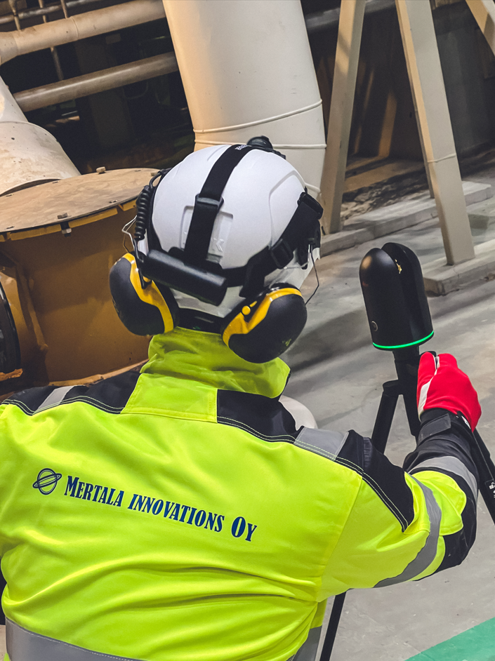
Laser scanning is based on laser beam distance measurement technology, while 3D scanning can be based on lasers or photography. To clarify the differences in our services, on this website, laser scanning refers to measurements made with a stationary laser scanner. 3D scanning, on the other hand, refers to scanning smaller objects, approximately less than 4 meters in length, using a handheld 3D scanner.
Laser Scanning

3D Scanning

What are the benefits of laser scanning?
Laser scanning allows a rapid creation of a 3D model or a layout of a space. The 3D model can be used, for example, as a basis for planning space modifications. In a factory environment, for instance, it can help plan the routing of pipelines or verify the fit of new machinery or entire production lines without the need for manual measurements on-site.
Laser scanning is also used for measuring individual equipment and machines and locating their interfaces. In a factory environment, there are often decades-old machines for which up-to-date documentation may not exist. Laser scanning provides easily accessible data for modeling and documenting the equipment.
Who can use the point cloud model?
Laser scanning produces a point cloud model, consisting of hundreds of thousands or even millions of individual points in space. Point cloud models can be easily processed on a computer screen using various software programs such as NavisWorks, Autodesk ReCap, or Faro Scene. Point cloud models can also be opened in traditional design softwares like SolidWorks and Autodesk Inventor. There are also numerous free viewing programs available for handling point clouds, such as Leica Truview, NavisWorks Freedom, CloudCompare, or MeshLab. This means that clients can manipulate point cloud models without investing in software.
In a point cloud model, users can, for example, take critical measurements and import existing 3D models into the point cloud model. This allows, for instance, verifying the fit of new equipment within a space.


Point Cloud in a Service Project
Point clouds are often used directly to support design projects, ensuring compatibility of new plans with an existing environment. The data collected by scanning is transferred as a point cloud to the design software, where 3D models can be imported and potential clashes examined. This method allows utilization of point clouds with minimal post-processing of scanning data.
Hauling Route Planning
Factory environments are often crowded with large equipment and structures. The hauled equipment are often complex in geometry, and hauling paths are filled with other equipment, pipes, and cable trays, making it challenging to move the equipment to its designated location. In a point cloud, the equipment hauling path can be simulated by moving the equipment model within the point cloud meter by meter, ensuring that no collisions occur.
As Built -modeling
"One of the most typical uses of laser scanning is utilizing the point cloud for layout planning. As-Built modeling refers to the actual CAD modeling based on the point cloud model, where structures and equipment are represented as solid features. As-Built modeling is done by converting a point cloud model, consisting of thousands of points, into a fixed CAD format that can be modified using common design software. Other 3D models can also be easily incorporated into the As-Built model to complement it. An example of As-Built modeling is our customer story where we laser scanned the power electronics and nuclear engineering laboratories at Lappeenranta University and created As-Built models from them.
The Basic and Advanced levels of modeling
The accuracy of As-Built modeling depends on the requirements of the model. In the upper right image, the nuclear engineering laboratory at Lappeenranta University is modeled very accurately, up to so-called Advanced level. Rails, pipes, and equipment are modeled very close to reality. The model also accurately mimics the actual color scheme of the space. Manufacturers' own 3D-models have been imported into the space. This results in a visually appealing outcome that can be used not only for space planning but also for presentation purposes.
The lower image shows the model of the power electronics laboratory at Lappeenranta University, created at the Basic level. In this case, the need was to generate rough ‘placeholder’ blocks for cabinets, equipment, and structures. These blocks serve only to occupy the necessary space, allowing for spatial planning by moving the blocks around. Basic-level modeling is sufficient for most purposes, though selected pre-agreed elements can be modeled in more detail.
The Basic and Advanced levels are precision levels defined by Mertala Innovations, which are explained in further detailed on the page below. The difference between the levels is reflected in the amount of work required. In the presented examples, modeling at the Basic level only took about one working day, whereas creating a precise and visually appealing Advanced model took approximately a week of work.


Pricing of Laser Scanning
The price of laser scanning depends on the size and complexity of the site. In an industrial environment, it is usually possible to laser scan areas of about 500–1500 m² per day, whereas several thousand square meters per day can be scanned in open outdoor areas. The cost of one day of laser scanning and post-processing starts from €2500 + VAT. The result is a clean and accurate point cloud model in the desired file format, which the client can use with free software, for example. The point cloud can be tied to the client’s preferred coordinate system.

Reverse Engineering and Digital Twin
3D scanning allows for the rapid creation of highly accurate 3D models of geometrically complex objects. Reverse engineering refers to the process of digitally modeling a physical object. One typical need for reverse engineering arises when a device manufacturer no longer supplies parts for a particular device, but there is still a need for those parts. In such cases, a part can be scanned, manufacturing drawings can be created, and the part can be produced by a machine shop. The fastest way to replicate a physical object is through 3D scanning and 3D printing of the model. This allows for the reproduction of a part in as little as a couple of days. Another common need for 3D scanning of a part arises when the manufacturer charges high prices for spare parts, and the part could be produced independently at a fraction of the cost.
Quality Control
3D scanning can be utilized, for example, in quality control of cast or welded structures, failure analysis, and in the creation of measurement and deviation reports. In quality assurance, the scanned model is compared to the original 3D model by overlaying them, allowing for the examination of discrepancies between the physical object and the ideal models. Software used for quality assurance provides visual reports, such as color maps, to illustrate deviations.
Laser Scanning and 3D Scanning Equipment


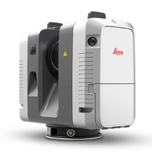
Leica RTC360
- Accuracy 1.9 mm, when distance is below 10 m
- Very fast scanning
- 360° photos
- Colored point clouds
Leica BLK360
- Accuracy 4.0 mm, when distance is below 10 m
- Medium-speed scanning
- Light and small
Creaform HandySCAN 307™ Elite
- Accuracy 0.04 mm
- Scanning of a small object in minutes
- Real-time evolving 3D model

Lauri Rauhala
Expert in 3D scanning
Ask for more information from our experts in 3D scanning related matters!
firstname.surname@mertalainnovations.fi
050 536 6726

